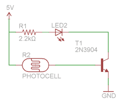
This is a circuit whose light will turn on once it is presented to murkiness. So it's a light that will go ahead when it gets dull, for example, at evening.
This is amazingly valuable for individuals who may live in a house that have vision issues and need the lights to consequently turn on when it gets dull. It's likewise extremely helpful for elderly individuals who live in a home who may experience issues strolling to turn on lights when it gets to be dull.
In our circuit, we will turn on a light when the level of light achieves a specific level of obscurity. Along these lines, the place where we put this circuit will dependably be lit up, either by the common light of the day or by the light of this circuit turning on when it gets to be dim.
Segments Needed

Photoresistor
330KΩ Resistor
2N3904 NPN Transistor
Driven
2 AA batteries or DC Power Supply
What we will use for this circuit is a photoresistor. Photoresistors are likewise called light-subordinate resistors (LDRs). This can be gotten at digikey at the accompanying connection: Tayda Electronics-Photoresistor. In the event that you don't have a photoresistor, quite recently make a point to utilize one that has a dull resistance of at least 2mω and a light resistance of around 20-30KΩ.
A photoresistor is a resistor whose resistance changes as indicated by the measure of light that it is presented to. At the point when presented to aggregate haziness, the photoresistor's resistance is high. This is called its appraised dim resistance. For instance, for our situation we are utilizing a 2MΩ photoresistor. This implies when presented to aggregate murkiness, its resistance will be around 2MΩ. As the photoresistor is presented to expanding measures of light, its resistance starts to drop fundamentally. There is another rating on the datasheet named cell resistance @ illuminance. This is the resistance that the photoresistor will drop to when presented to brilliant light, regularly 10 lux. This is additionally called the light resistance (since it is the resistance the photoresistor has when presented to brilliant light). For our photoresistor, specifically the phone resistance @ illuminance is 20-30kω. This implies the resistance of the photoresistor will drop to 20-30KΩ when presented to 10 lux level of light.
So a photoresistor is fundamentally a gadget that radiates high resistance at dim light levels and low resistance at high light levels. Being that it does this, it can go about as a sensor for light, or a photosensor.
With the photoresistor going about as the light sensor, the other critical part is the 2N3904 transistor. The transistor in this circuit will go about as an intensifier, increasing current so that adequate current is delivered to light the light.
Any sort of LED can be utilized for this circuit.
The power we will use for this circuit is a 3 volts, which can be acquired from either 2 "AA" batteries in arrangement or from a DC control supply set to this voltage.
Along these lines, for this circuit, 3 volts is driving the circuit. This 3 volts is in parallel to a 100KΩ resistor and the photoresistor. Amidst these 2 segments is associated the base of the NPN 2N3904 transistor.
This is the means by which the circuit works:
At the point when presented to brilliant light, the photoresistor's resistance is low. It drops to around 20-30KΩ. Current goes through the 100KΩ resistor and afterward has 2 ways it can either experience the base of the transistor or experience the photoresistor. The base of the resistor to the authority has a resistance of around 400KΩ. Current dependably takes the easy way out. At the point when the photoresistor is presented to brilliant light, its resistance is around 20-30KΩ, which is altogether not exactly the 400KΩ of resistance the base of the transistor has. In this manner, the greater part of the present will experience the photoresistor and next to no will go to the base of the transistor. So the base of the transistor is circumvent. Accordingly, the transistor does not get enough present to turn on and control on the LED. Along these lines, the LED is off when there is a considerable measure of light in the environment.
Nonetheless, when it starts to get dull, the photoresistor's resistance turns out to be high. Its resistance goes up to more than 2MΩ of resistance. This makes a high-resistance way. Being that 2MΩ is altogether more prominent than the 400KΩ of resistance that the base of the transistor offers, a large portion of the present will experience the base of the transistor. This implies current does not experience the photoresistor when it is dim, because of this high resistance. Rather present experiences the 100KΩ resistor and through the base of the transistor. The transistor gets enough present to control on and turn on the LED associated with the authority terminal.
So this is the manner by which a dull actuated light circuit can work.
Once more, as usual, varieties of this circuit should be possible. Rather than utilizing am LED, we can utilize some other kind of lighting installation, for example, a light. You might need to utilize a brilliant LED. Then again you can utilize some other different lighting source. You might need to utilize numerous lights, so you can put diverse lights in parallel in each other. All that would be required is a conformity in the voltage and current of the circuit. Redo the circuit as indicated by your requirements and inclinations.

No comments:
Post a Comment